In this Tutorial, we are going to learn all the basics needed to start your project with PIC Micro controllers in just 4 steps.
Step1:Building your own programmer.
Step2:Creating a PIC program using an Integrated Development Environment
Step3:Flashing your program
Step4:Verifying your program
Step1:Building your own programmer.
Step2:Creating a PIC program using an Integrated Development Environment
Step3:Flashing your program
Step4:Verifying your program
Step1:Building your own programmer
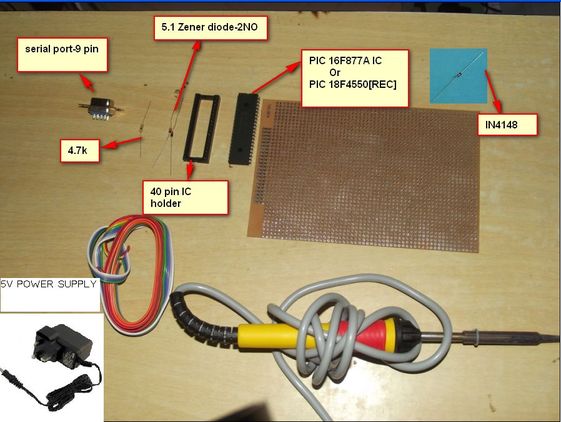
I)Get the following components.
II)Get the pin diagram of the PIC Micro.
This programmer is tested for PIC 16F877A and 18F4550 anyhow the pin configuration for both the Micro controller remains the same .
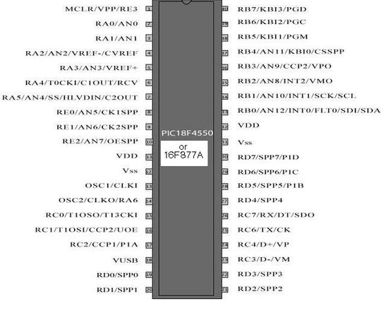
III)Connecting Power supply to the Microcontroller.
Shot Both of the VDD pins[Pin11----PIN32] -->Connect to +5v of the Adapter
Shot Both of the VSS Pins[Pin12----Pin31]--->Connect to Gnd of the Adapter
Note:Use the base of the Micro controller only because soldering heat may affect the micro controller.
IV)Circuit of the PIC programmer
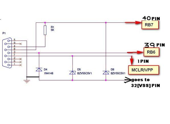
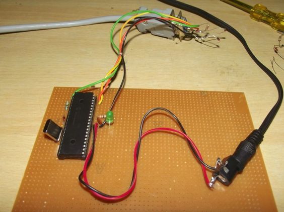
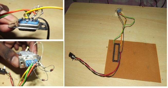
V)Our simple programmer should look like this
Step2:Creating a PIC program using an Integrated Development Environment
You can create project using a famous compiler with all built-in libraries.Check the Below Video.
Program:
void main()
{
TRISB=0x00;//Making PORTB as OUTPUT PORT
while(1)
{
delay_ms(1000);
PORTB=0X00;//0v on PORTB
delay_ms(1000);
PORTB=0XFF;//5v on PORTB
}
}
Step3:Flashing your Program
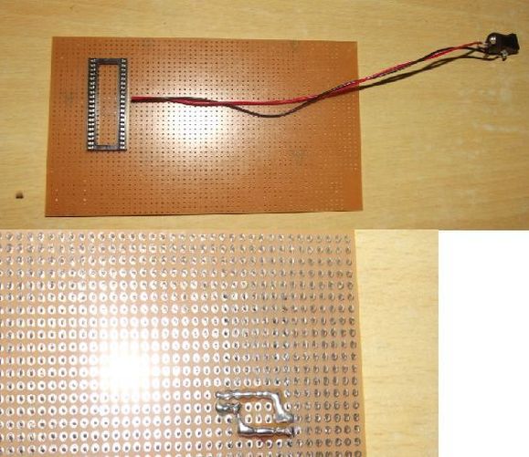
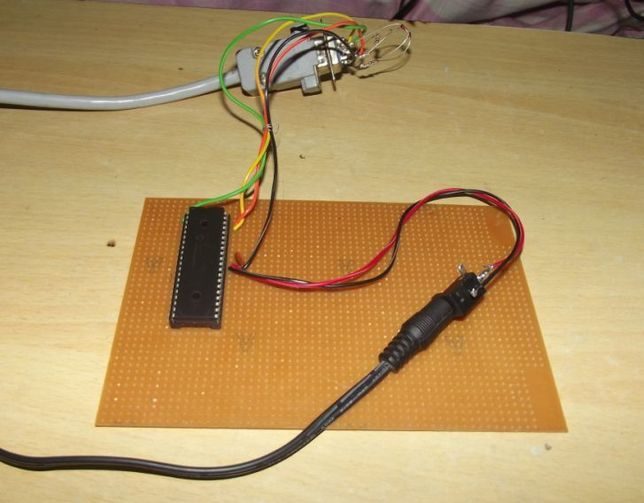
I)Now Connect your Micro controller to the 40 Pin IC base.
Connect the serial port and Power supply like the Image below
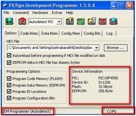
II)Install the PICPGM tool and check for the detection of the Programmer and Micro.
You can download it from here http://members.aon.at/electronics/pic/picpgm/download.html
for PIC16f877A it will be detected as "PIC: PIC16F877A" in Device information.
III)Browse the Hex file and flash it to the Micro controller.
For Pic 16F877A the verification may fail ,but it will be successfully programmed on to it.
If you are not Satisfied with the Error message then, you should use the IC-prog tool to flash it.
This will give a Positive result "Verified Successfully".
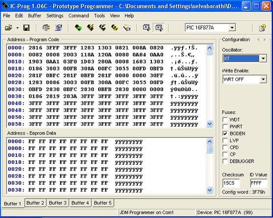
While programming using Ic-prog tool ,set the following configuration as below .
Step4:Verifying your program
I)Now,its time to verify it.
You need the following components to run and verify your program from the Microcontroller.
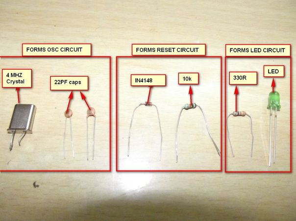
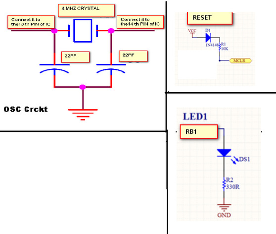
II)Circuit for Connecting OSC circuit,Reset circuit,Led circuit,
Connect as per the circuit.
III)Finally your programmer should like this.
Just disconnect the serial port .You should able to see LED blinking as we programmed.
Note:Power should be connected